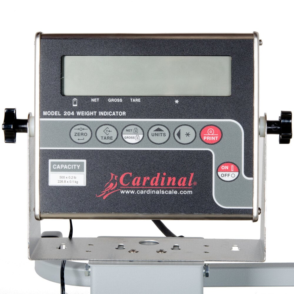
Cardinal Scale 220 Manual
admin


Weight Indicating Instrument. Operation Manual. H bridge mosfet driver circuit. 8545-M409-01 Rev B. PO BOX 151 WEBB CITY, MO 64870. Printed in USA. PH (417) 673-4631 - FAX (417) 673-5001. Thank you for purchasing the Cardinal 777 Programmable Weight Indicating Instrument. 280mm W X 245mm H X 220mm D. Be a part of the world's greatest classic car auction. Learn when Barrett-Jackson's next event is and get your tickets today! Technical Support: Ph: 866-254-8261 y techsupport@cardet.com. Installed and used in accordance with the instruction manual, may cause interference to radio communications. It has been tested and found to. Model Numbers 200, 205, 210, 210-FE, 215 and 220. Serial Number EXXXYY-ZZZ.
Cardinal 220 Scale Manual

Cardinal Scale 210 Manual
- 6Table of Contents
- 8Foreword
- 10System Configuration
- 111 Operational Overview
- 11Control Description
- 12Remote Controller
- 13Turning the Power On/Off
- 14Raising, Lowering the Transducer
- 15Adjusting Screen Brilliance, Panel Dimmer
- 16Selecting a Display
- 17Adjusting the Gain
- 17Basic Menu Operation
- 192 Horizontal Mode
- 20Typical Horizontal Mode Display
- 21Selecting the Range
- 22Selecting Sector Width
- 23Selecting Train Center
- 23Selecting the Tilt Angle
- 24Bottom Echo and Tilt Angle
- 24How to Discriminate Fish Echoes From the Bottom
- 25Points to Consider
- 25Tilt Angle for Surface Fish
- 27Selecting the Training Speed
- 27Finding Echo Position With the Cursor
- 28Event Marker
- 29Depth and Horizontal Range Markers
- 30Adjusting the Picture
- 31Suppressing Bottom Tail
- 35Target Lock
- 36Position Mode
- 37Echo Mode
- 39Horizontal Menu Overview
- 41Interpreting the Horizontal Display
- 42Sample Echo Displays
- 42Bottom Echoes
- 43Fish Schools
- 44Sea Surface Reflections
- 45Noise and Interference
- 46Combination Display Examples
- 513 Vertical Fan Mode
- 51Operational Overview
- 52Typical Vertical Fan Mode Display
- 53Selecting the Range
- 54Selecting Train Center
- 55Selecting Display Sector
- 56Selecting Sector Center
- 57Selecting the Training Speed
- 57Finding Echo Position With the Cursor
- 58Event Marker
- 59Depth and Horizontal Range Markers
- 60Adjusting the Picture
- 61Suppressing Noise and Interference
- 62Vertical Menu Overview
- 63Interpreting the Vertical Fan Display
- 694 Echo Sounder Mode
- 69Operational Overview
- 70Typical Echo Sounder Display
- 71Selecting the Range
- 72Train Direction
- 72Selecting Tilt Angle
- 72Selecting Picture Advance Speed
- 73Measuring Range By Cursor
- 73Event Marker
- 74Inscribing the Event Marker
- 74Deleting All Event Markers
- 75Range Marker
- 75Adjusting the Picture
- 78Echo Sounder Menu Overview
- 815 Menu Operation
- 81COM1 Menu
- 82Com1 Menu Description
- 83COM2 Menu
- 84Short-cut Menu, Preset Menu
- 86Preset Key
- 89SYS Menu
- 90System Setting 1 Menu Description
- 92System Setting 2 Menu Description
- 97Echo Sounder Mode Range Settings
- 98Track Range Settings
- 99Color Palette
- 100System Backup
- 100Loading Backup Data
- 101Transducer Frequency Adjustment
- 101Demonstration Mode
- 102Restoring All Default Settings
- 1036 Maintenance, Troubleshooting
- 103Preventive Maintenance
- 103Cleaning the Equipment
- 104Hull Unit Maintenance
- 105Transducer Maintenance
- 105Fuse Replacement
- 106Troubleshooting
- 107Error Messages
- 108Diagnostics
- 110Test Pattern
- 111Menu Tree
- 113Specifications
- 117Index